Loading…
Learn80 practical guides
Evidence-led bicycle setup guides
Plain-language guides tied to published sources, product conventions and stated limits. See what is measured, what is assumed and what remains uncertain.
Understandthe claim
Measurethe baseline
Re-checkone change

Research, translated for the workbench
Understand the claim, see its limit, then make one change you can measure again.
Choose your path
Start with the question you actually have
Browse by question below, or find a named bicycle part or recording method in the reading-path directory. Each guide keeps its sources and limits.
Find a bicycle reference
Which part or method are you reading about?
19 reading paths, grouped by subject. Open only the ones you need; each keeps its complete steps, source boundaries and next links. Opening a path does not run a tool or choose a component.
Saddle, bars and contact references
Identify the point, plane and interface before combining contact dimensions.
Saddle dimensions, tilt and railsWidth, named saddle points and clamp interfaces.Reading path
Rigid seatposts and insertionOffset, diameter, adapters and exposed length.Reading path
Dropper travel and saddle statesExtended and collapsed intervals, insertion and routing.Reading path
Drop bars, hoods and brake leversBar dimensions and independent left/right control references.Reading path
Flat and MTB handlebarsClamp, grip stations, rise, sweep and roll.Reading path
Aerobars, armrests and extensionsIndependent interfaces, pad coordinates, width and grip points.Reading path
Stem, spacers and cockpit coordinatesHead angle, stem conventions and named clamp points.Reading path
Frame, wheels and suspension
Separate chart dimensions, mounting interfaces and the declared bicycle state.
Frame charts and BB referencesStack, reach, top tube, seat angle and ground references.Reading path
Fork length, trail and axle spansSteering-axis conventions and independent centre distances.Reading path
Tyre sizes, rims and rolling referencesNominal size, mounted width, bead permissions and radius.Reading path
Axles, hub spacing and disc rotorsRetention system, named faces, threads and brake interfaces.Reading path
Headsets, bearings and crown racesSHIS interfaces, contact angles and axial stack stations.Reading path
Rear shocks and loaded referencesEye-to-eye, stroke, hardware, wheel travel and sag.Reading path
Suspension fork travel and sagActual movement, loaded conditions and frame versus ground pose.Reading path
Cranks, pedals and gearing
Keep length, receiving interfaces and transmission arithmetic separate.
Crank length and pedal referencesMarked length, spindle distance, Q-factor and stack.Reading path
Bottom brackets, spindles and chainringsShell standards, bearing stations and mounting identity.Reading path
Shoes, cleats and pedal interfacesIndependent contacts, named cleat coordinates and free movement.Reading path
Gear ratios, cassettes and derailleursDevelopment, percentage steps, freehubs and capacity limits.Reading path
Camera method and evidence
Understand the recording convention before reading an angle or comparison.
Recording setup, angles and repeatabilityPrepare the view, name the angle, read quality and repeat independently.Reading path
Browse all 80 guides
The complete library, grouped by measurement question. The reading paths above are another way into these same guides, not a separate set of recommendations.
Topic 0123 guides
Build a baseline
Start with measurements, understand the limits, and record a position you can restore.
One arm. Two independent records.
- Physical reference
- 165 mm
- Displayed setting
- 170 mm
Original schematics, not to scale or a real device screen. No sensor is connected, setting changed, acknowledgment checked or power accuracy verified.
Pedal power settingFeatured field guide
Pedal power-meter crank length: physical arm, device setting and readback are separate
Identify the installed arm and exact pedal system, find which controller supplies its crank-length value, and preserve a readback record without confusing calibration, scale factors or a changed bicycle with a verified setting.
Read the complete guideName the axle line. Then name the baseline.
Original schematic, not to scale, an actual trainer or mounting instructions. No block height, tolerance, compatibility or riding approval is inferred.
02Trainer referenceIn-depth
Level a bike on a trainer for measurement: axle height is not camera level
Before measuring or filming, identify the intended bicycle reference, the actual axle stations and the support condition. Separate trainer pitch, mixed-wheel geometry and phone orientation without prescribing a block height.
Read guideSame floor. Different book edges.
Original endpoint schematic, not to scale or a body drawing. Examples are not body-size pairings, targets or measurement precision. Never force contact or copy these values into your inputs.
03Body inputsIn-depth
How to measure cycling inseam and height before using a bike calculator
Measure the person before entering a number: distinguish cycling inseam from trouser size, choose the correct book edge, repeat the readings and enter centimetres or total inches without inventing a fit target.
Read guideThree endpoints. Two declared states.
Original schematic; not to scale. No physical measurement, preferred travel, clearance, control function, compatibility or installation is established.
04Dropper referencesIn-depth
Dropper post travel, total length and stack height: name the endpoints and state
Separate moving travel, extended total length, collapsed residual height and the frame collar reference. A familiar size or stack label does not identify every dimension.
Read guideA visible interval is not a movement capacity
Original schematic; not to scale. No physical measurement, sag target, pressure, part permission, adjustment or installation is supplied.
05Front suspension referencesIn-depth
Suspension fork travel vs exposed stanchion length: name the movement, not the visible tube
Separate specified travel, visible upper tube, tube diameter, axle-to-crown length and an observed marker displacement before interpreting a fork record.
Read guideSame compression. Different denominator.
Original schematic; not to scale. No physical measurement, sag target, pressure, part permission, adjustment or installation is supplied.
06Front suspension referencesIn-depth
Suspension fork sag measurement: keep millimetres, denominator and loaded condition together
Read an existing front-sag observation without confusing settled compression, exposed tube, a ride marker or an unsupported percentage target.
Read guide07Drivetrain referencesIn-depth
Bicycle gear ratio, gear inches and development: three different numbers
Read front/rear tooth counts, distinguish dimensionless ratio from distance per crank turn, and keep wheel circumference and crank length in their own models.
Read guide08Drivetrain referencesIn-depth
Gear range versus gear steps: why the percentage and cadence need a denominator
Compare endpoints, the complete tooth sequence, overlapping combinations and inverse cadence changes without treating gear count or range as a riding recommendation.
Read guideHeadset reference · not to scale
Two interfaces. Not one diameter.
Upper and lower nominal families are separate; no tolerance or replacement permission is inferred.
09Headset referencesIn-depth
Headset standards: read SHIS, EC, ZS and IS as separate interfaces
Decode upper and lower headset references without confusing nominal head-tube codes, bearing dimensions and fork interfaces.
Read guideHeadset reference · not to scale
Size is a record, not a single number.
Separate dimensions and named contacts. Matching lengths alone do not establish compatibility.
10Headset referencesIn-depth
Headset bearing dimensions and angles: keep diameter, height and contacts separate
Build a precise bearing reference without treating one diameter, an angle pair or a headset family as an interchangeable-part certificate.
Read guideHeadset reference · not to scale
Receiving seat ≠ bearing-facing race.
Fork receiving seat and bearing-facing contact are separate; integrated construction must be established.
11Headset referencesIn-depth
Crown race vs fork race seat: identify the part, the support and the bearing contact
Separate fork-seat diameter, crown-race identity and lower-bearing contact without adding a ring or approving an adapter from a size label.
Read guideHeadset reference · not to scale
Add named intervals once.
Fictional axial intervals, not steerer preparation. Unknown contributions stay unknown; inclusive terms are counted once.
12Headset referencesIn-depth
Headset stack height vs head-tube length: reconcile the axial stations
Keep upper/lower external stack, head-tube length, spacers and stem-clamp height separate before interpreting a steerer or cockpit dimension.
Read guideRear-shock reference · not to scale
Axis distance ≠ movement capacity.
Fictional extended axis distance L0=210 mm; applicable stroke S=50 mm.
Declared axial compression s=10 mm → axis distance L=200 mm; 10/50=20%.
Neither body outline, visible shaft nor rear-wheel travel is inferred. No target or replacement approval.
13Rear suspension referencesIn-depth
Rear-shock eye-to-eye vs stroke: two lengths, different endpoints
Decode a rear-shock size without confusing mount-axis distance, usable stroke, exposed shaft and rear-wheel travel.
Read guideRear-shock reference · not to scale
Name the mount, then the hardware.
Standard: upper/lower eyelet axes. Trunnion: upper side-mount axis and lower eyelet axis.
Separate fictional hardware width W=30 mm and bolt diameter D=8 mm; no conversion or tolerance.
Mount family, hardware identity, receiving permission and full-motion clearance remain independent.
14Rear suspension referencesIn-depth
Rear-shock mounts: standard eyelets, trunnion and independent hardware
Identify mount axes, hardware width and bolt diameter without treating a size label or adapter arithmetic as assembly approval.
Read guideRear-shock reference · not to scale
Same totals. Different intermediate motion.
Fictional main-frame-relative vertical quantity W; not axle-path length or manufacturer kinematics.
A: W=3s. B: W=2s to s=20; then W=40+(11/3)(s−20). Both end at s=50 mm, W=150 mm.
At s=10 mm: A gives 30 mm, B gives 20 mm. Full-interval mean 3 is not a local ratio; B has an artificial corner.
15Rear suspension referencesIn-depth
Rear-shock stroke vs wheel travel: why one ratio is not a linkage
Separate axial shock movement, rear-axle path and vertical displacement; test why equal total travel does not determine loaded geometry.
Read guideRear-shock reference · not to scale
An observation needs its condition.
Fictional L0=210 mm and loaded L=200 mm → compression 10 mm; with S=50 mm, fraction 20%.
Unknown usable stroke → fraction unknown, not zero. Marker after a ride ≠ an established settled load.
Wheel sag, BB height, front condition and ground-relative geometry are not inferred. No sag or pressure prescription.
16Rear suspension referencesIn-depth
Rear-shock sag vs wheel sag: record the loaded reference, not a target
Keep settled shock compression, usable stroke, rear-axle displacement and marker history distinct before comparing geometry.
Read guideMeasurement field guide
One origin. Two components.
BB centre = origin · X forward · Y up
Bar X 480 mm · Bar Y 605 mm
Fictional points; schematic, not to scale.
17Measurement checklistIn-depth
Bike fit measurements: record a repeatable bicycle setup
A practical measurement checklist: name the saddle and cockpit points, choose a bottom-bracket datum, repeat readings and keep an honest record without inventing fit targets.
Read guideMeasurement field guide
Keep all readings, not just a mean.
Reading 1740mm
Reading 2743mm
Reading 3741mm
Observed span: 743 − 740 = 3 mm
Mean ≈ 741.3 mm; not guaranteed accuracy
Fictional readings, not a fit result.
18RepeatabilityIn-depth
Repeatable bike measurements: compare readings, not noise
A practical repeatability protocol for manual bike coordinates: relocate the tool, keep each reading, check the reference and separate observed spread from a claimed setup change.
Read guideSaddle reference field guide · not to scale
New impression. Independent reading.
Fictional readings: 120 mm and 124 mm
Difference 4 mm · mean 122 mm
Agreement does not establish anatomical accuracy or an ideal saddle.
19Saddle referencesIn-depth
Measure sit-bone width at home: repeat the impression, not just the ruler
Make independent centre-to-centre observations, keep unclear marks unresolved and distinguish a posture-labelled starting range from a verified saddle fit.
Read guideWheel reference guide · not to scale
A name is not the outside circle.
37-622: nominal width 37 mm; bead-seat diameter 622 mm.
Fictional radial extension 35 mm → outside diameter 692 mm; radius 346 mm.
The radial extension is declared—not inferred from the 37 mm width. No assembly is approved.
20Wheel referencesIn-depth
Bicycle tyre sizes explained: ETRTO, 700C, 650B and 29 inch
Read the bead-seat diameter before comparing wheel names. Separate a tyre’s nominal width, rim interface, mounted outside diameter and frame permissions without guessing that 700 means 700 mm.
Read guideWheel reference guide · not to scale
Width and height use different directions.
Fictional profile: lateral width 40 mm; radial extension 35 mm.
The rim’s internal and external spans are also separate quantities.
Schematic only. No real casing shape, width correction or clearance threshold is predicted.
21Wheel referencesIn-depth
Tyre width vs inner rim width: measure the mounted envelope
Nominal tyre width, rim internal width and maximum mounted width are different dimensions. Keep casing, tread, radial height and clearance questions separate before comparing a setup.
Read guideWheel reference guide · not to scale
Travel is not axle height.
Fictional rolling observations: 2158, 2162, 2160 mm → mean 2160 mm; span 4 mm.
Equivalent ideal-circle radius = 2160 ÷ 2π ≈ 343.8 mm.
This is not a measured loaded axle height, instrument accuracy or compatibility approval.
22Wheel referencesIn-depth
Wheel circumference vs loaded radius: choose the right measurement
A computer’s distance per wheel revolution, an ideal outside-circle radius and a loaded axle height are not interchangeable. Record a rolling test and keep geometry-model assumptions separate.
Read guide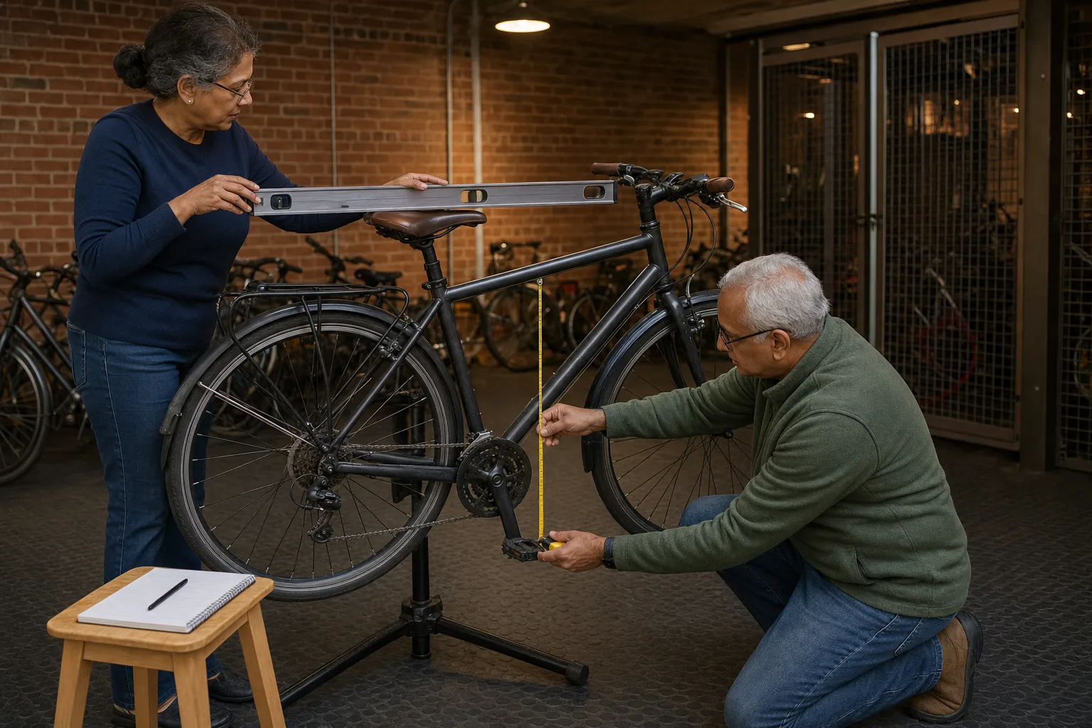
23MethodIn-depth
Change one thing, then re-check
The fastest way to a good fit is small, reversible steps you can actually measure.
Read guideTopic 0237 guides
Shape the position
See how saddle, cranks and cockpit change the geometry between rider and bike.
Axial drop is not vertical drop.
Original schematic; not to scale. No physical measurement, preferred travel, clearance, control function, compatibility or installation is established.
Dropper referencesFeatured field guide
Dropper saddle-height references: full extension, lowered state and BB coordinates
Keep frame-collar-to-rail length separate from a named saddle-surface point. Axial drop changes both horizontal and vertical projections on an angled shaft.
Read the complete guideFixed frame points. A different ground pose.
Original schematic; not to scale. No physical measurement, sag target, pressure, part permission, adjustment or installation is supplied.
02Front suspension referencesIn-depth
Fork sag and bicycle geometry: distinguish frame-fixed points from the ground-relative pose
Follow one explicitly ideal rigid-rear construction to see why fork compression, frame pitch, BB height and cockpit X/Y are not the same change.
Read guideAero contact reference · not to scale
Different receivers. Independent permission.
The linked Vuka Clip manual separately names 31.8 mm basebar and 22.2 mm extension interfaces; it excludes 22 mm extensions for that system.
Receiving-bar permission, actual contact region and the complete pad/riser support remain separate checks.
0.2 mm arithmetic is not a tolerance, shim design or approved assembly.
03Aero contact referencesIn-depth
Aerobar clamp and extension compatibility: identify every receiving interface
A basebar clamp, extension receiver and armrest assembly have different requirements. Keep exact model permissions and unresolved physical checks separate before reading an aero cockpit dimension.
Read guideAero contact reference · not to scale
Frame ≠ clamp ≠ named pad.
Fictional BB-relative F=(390,560), B=(480,605), P=(460,650) mm. X forward, Y upward.
Local B→P=(−20,+45) mm. A flat 100 mm pad line: rear R=(410,650), centre P=(460,650).
Different origins and endpoints; not frame sizing, pad selection or a physical installation.
04Aero contact referencesIn-depth
Aerobar pad stack and reach: BB coordinates are not frame or bracket offsets
Name the pad point, surface, load state and origin before comparing an aero cockpit. Centre, rear edge, holder, basebar and frame stack/reach do not describe the same endpoint.
Read guideAero contact reference · not to scale
Keep each side, not just a span.
Fictional Z positive toward rider’s left: L +110 mm, R −95 mm → lateral centre span 205 mm; midpoint +7.5 mm.
Separate parallel 80 mm pad shapes: outside span 285 mm; inner gap 125 mm.
Projected references only; not direct 3D distance, contact width or an ideal armrest position.
05Aero contact referencesIn-depth
Aerobar armrest pad width: centre span, edges and each side’s station
Pad width is not extension spacing, pad-shell width or an ideal arm position. Preserve left/right lateral coordinates, endpoint conventions and yaw before comparing spans.
Read guideAero contact reference · not to scale
The tube is not the grip point.
Fictional P=(460,650) and G=(670,700) mm → local p=(210,50) mm; direct planar gap ≈215.9 mm.
Separate mathematical +10° rigid rotation about fixed P: p′≈(198.1,85.7) mm; G′≈(658.1,735.7) mm.
No actual hinge, missing lateral coordinate, bend geometry, cutting plan or physical adjustment is supplied.
06Aero contact referencesIn-depth
Aerobar extension length vs grip position: the tube is not the hand point
Stock length, exposed length and a named grip coordinate have different endpoints. Keep bends, pad-to-grip projections and orientation visible without turning a length into a cutting or fit instruction.
Read guideMeasurement field guide
Name the point before the number.
Reference point: X −90 mm · Y 735 mm
Direct BB distance ≈ 740.5 mm
Fictional geometry; schematic, not to scale or a target.
07Saddle referencesIn-depth
Saddle measurement points: nose, centre and reference lines
Why two saddle-height or setback numbers can disagree: distinguish the saddle nose, a named top-surface reference and the BB datum before comparing a setup.
Read guideMeasurement field guide
Frame ≠ bar clamp ≠ hood.
F head tube: 390 / 560 · B clamp: 480 / 605 · H hood: 550 / 620
All X / Y values in mm from the same BB
Fictional points; not an approved build.
08Cockpit coordinatesIn-depth
Frame stack and reach vs handlebar and hood coordinates
Frame geometry ends at the head tube; your controls do not. Learn which endpoint each number describes before comparing frames or passing a measured cockpit target to a tool.
Read guideCockpit field guide · schematic
One label. Resolve the reference.
Fictional conventional steerer: h = 73°
90 − 73 − 6 = +11° actual horizontal angle
Conditional geometry, not a universal conversion or fit target.
09Cockpit geometryIn-depth
Stem angle and rise explained: the label is not the installed angle
Understand nominal rise, steerer-based angles and the actual stem centreline angle from horizontal before using a stem comparison calculator.
Read guideCockpit field guide · schematic
Up the steerer means up and back.
Fictional h = 73° · added contribution s = 20 mm
Unrounded vector: X ≈ −5.8 mm · Y ≈ +19.1 mm
Not a permitted stack, installed measurement or spacer recommendation.
10Cockpit geometryIn-depth
Stem spacers change reach as well as height: read the X/Y effect
Understand why headset spacers travel up and back along the steerer, how to separate stem and spacer effects, and why a calculator range is not a safe spacer limit.
Read guideCockpit field guide · schematic
Same clamp. Different point.
Fictional fixed-point offset: 70 mm X / 15 mm Y
Upward 10° rotation → 66.3 mm X / 26.9 mm Y
Not a real hood, an adjustment instruction or the calculator's proxy.
11Cockpit geometryIn-depth
Handlebar reach and drop are not your hood position
Separate handlebar-shape dimensions, bar rotation, installed hood coordinates and brake-lever reach before comparing a road or gravel cockpit.
Read guidePedal interface field guide · schematic
Two interfaces. One identified assembly.
Shoe → cleat: mounting pattern and approved parts
Cleat → pedal: exact engagement system and generation
Bolt count or colour alone is not compatibility approval.
12Pedal interfaceIn-depth
Cycling cleat and pedal compatibility: the shoe holes are only half the check
Identify the shoe mount, exact cleat and pedal generation before copying a position. A three-bolt sole, a colour or a successful click-in does not prove compatibility.
Read guidePedal interface field guide · schematic
A window is not a mounted angle.
Fictional symmetric total float: 6° = −3° to +3°
Mounted rotation, retained movement and release are separate.
Schematic, not to scale or a direction to adjust a cleat.
13Pedal interfaceIn-depth
Cleat float vs rotation and release tension: three different settings
Separate a cleat's mounted angle, the rotational window while engaged and release force. Read total degrees and per-side degrees without turning a float label into an adjustment.
Read guidePedal interface field guide · schematic
Name both sides before adding.
Fictional Q 150 mm + left 53 mm + right 53 mm = 256 mm
Pedal-centre span is not automatically anatomical foot span.
Schematic, not to scale, an approved assembly or a stance target.
14Pedal interfaceIn-depth
Q-factor vs pedal stance width: name the endpoints before comparing millimetres
Crank Q-factor, a one-sided pedal offset and the distance between shoes are different widths. Learn the conventions and why a cleat's lateral move is opposite to the shoe's move.
Read guidePedal interface field guide · schematic
Same endpoints. Then subtract.
Fictional declared stack: A 12 mm · B 15 mm · B − A = +3 mm
Sole, insole and foot reference are not silently included.
Schematic, not to scale or an automatic saddle adjustment.
15Pedal interfaceIn-depth
Pedal and shoe stack height: compare the same assembly and endpoints
A pedal's stack is not the whole distance to the foot. Keep cleat, adapter, sole and insole references visible before comparing systems or re-checking a bicycle setup.
Read guideFrame chart field guide · not to scale
Same reach. Different horizontal span.
Fictional reach 390 mm · stack 560 mm
BB-through seat axis: 73° → ETT 561.2 mm; 74° → 550.6 mm
Ideal named axes only; not a curved-frame converter or size verdict.
16Frame chartIn-depth
Effective top tube vs reach: read the endpoints, not the frame label
Separate the actual tube, a virtual horizontal top tube and BB-relative frame reach. See why seat angle and chart reference height can change a length without changing frame reach.
Read guideFrame chart field guide · not to scale
Same upper axis. Different effective angles.
Fictional P1: X −150 / Y 650 mm → effective 77.0°
Fictional P2: X −185 / Y 750 mm → effective 76.1°
Upper axis 70.7°; BB-to-point angles differ. Y is vertical, not tape length.
17Frame chartIn-depth
Effective seat tube angle: the reference height changes the meaning
Distinguish the physical seatpost exit line from a virtual BB-to-reference angle. Keep the stated saddle height, frame setting and actual saddle coordinate beside each value.
Read guideFrame chart field guide · not to scale
Keep the standing station.
Fictional shod standing observation: 810 mm
Station A: tube 780 → gap 30 mm; B: tube 795 → gap 15 mm
Neither gap is a clearance approval. Post insertion is a separate check.
18Frame chartIn-depth
Bike standover height: measure the station, then check separate limits
Keep ground, tyre condition, standing location and footwear explicit. Standover clearance, seat-tube length and seatpost insertion are independent checks, not a single bike-size formula.
Read guideFrame chart field guide · not to scale
Two origins. One bottom bracket.
Fictional level equal axles: 350 − drop 70 = BB height 280 mm
Both supports +6 mm → BB height 286 mm; drop stays 70 mm
Static equal-wheel construction only; not pedal clearance or handling approval.
19Frame chartIn-depth
Bottom bracket drop vs height: keep the axle and ground references separate
Read frame-relative BB drop and ground-relative BB height without confusing either with saddle drop or pedal clearance. Account for actual tyres, geometry setting and unequal-wheel conditions.
Read guideSaddle reference field guide · not to scale
Same outside width. Different boundary.
Fictional outside span: 150 mm for both sections
Declared usable spans: A 130 mm · B 142 mm
Named illustrative boundary only; not a pressure map or a comfort ranking.
20Saddle referencesIn-depth
Saddle width vs usable support: the widest number is not the whole surface
Separate external width, manufacturer-defined effective width and a named longitudinal station. Compare shapes without turning a catalogue label into a pressure map.
Read guideSaddle reference field guide · not to scale
One saddle. Two measured lines.
Fictional front section: 0° · long bridge: +4°
Nose-up positive; changing the reference is not an adjustment.
No universal angle or physical installation is approved.
21Saddle referencesIn-depth
Saddle tilt on curved saddles: name the surface before reading the angle
Separate a front section, centre section and long bridge. Record bicycle alignment, tool placement and signed readings without prescribing one angle for every saddle.
Read guideSaddle reference field guide · not to scale
Section, clamp and zone stay separate.
Round 7×7 mm and oval 7×9 mm are distinct sections.
Fictional visible rail: 100 mm · marked zone: 60 mm
Dimensions alone do not approve a clamp, adapter or installation.
22Saddle referencesIn-depth
Saddle rails and seatpost clamps: 7×7 vs 7×9 is only the start of compatibility
Identify rail cross-section, material, exact clamp hardware and marked engagement limits before copying a saddle position. A number or apparent fit is not assembly approval.
Read guideControl reference field guide · not to scale
Same sections. Different endpoints.
Fictional bare circular sections: diameter 24 mm each.
Centre span 400 mm · outside 424 mm · inside 376 mm.
Conditional construction only; not a universal conversion or ideal bar width.
23Control referencesIn-depth
How to measure drop-handlebar width: hoods, drops and outside edges
Name the bar station and centre/edge convention before comparing road or gravel widths. Repeat a real span without turning shoulder breadth into an ideal size.
Read guideControl reference field guide · not to scale
Name the view. Then the angle.
Fictional front view: upper 400 mm · vertical span 100 mm · flare 12°.
Derived lower span ≈442.5 mm; a 50 mm vertical span gives ≈421.3 mm.
The top-view end direction is a separate construction, not a hood angle or assembly limit.
24Control referencesIn-depth
Handlebar flare vs outsweep and backsweep: read the plane and station
Separate whole-drop inclination, outward lower ends and swept tops. A shape label cannot reconstruct installed hood width or choose a gravel bar.
Read guideControl reference field guide · not to scale
Resting position ≠ engagement travel.
Fictional same-line example: resting gap 70 mm · movement 15 mm.
Gap at the observed event 55 mm; no travel target is supplied.
A resting gap is not a brake-function or clearance test. Exact controls and manuals matter.
25Control referencesIn-depth
Brake-lever reach vs free stroke: resting gap is not brake travel
Separate blade position at rest, movement before pad engagement and brake function. Identify exact controls before using a left/right gap comparison.
Read guideControl reference field guide · not to scale
One matched column is not the whole pair.
Fictional body-height means: L 622 mm · R 619 mm · difference +3 mm.
Resting blade gaps: L 70 mm · R 70 mm · difference 0 mm.
Height, declared angle axis, gap and brake operation remain separate observations.
26Control referencesIn-depth
Check hood and brake-lever symmetry: height, angle and gap stay separate
Build a repeatable left/right control record with mirrored features, declared angle axes and resting blade gaps. Visual alignment is not a functional or fit certificate.
Read guideCrank field guide · not to scale
Locate axes, not arm ends.
Fictional radius 170 mm → diameter 340 mm.
BB axis to pedal axis defines L; the visible outline is different.
Fixed-BB planar construction, not an ideal crank length or physical measurement.
27Crank referencesIn-depth
How to measure bicycle crank length: centres, markings and separate dimensions
Identify the BB and pedal axes, keep a stamped length separate from a ruler observation, and avoid confusing arm length with spindle length, Q-factor or pedal-circle diameter.
Read guideCrank field guide · not to scale
One assumption. Two contributions.
Fictional vertical model: crank 172.5→165 mm; saddle Y 740→747.5 mm.
Bottom gap 912.5 mm unchanged; top gap 567.5→582.5 mm (+15 mm).
With X −90 mm held fixed, direct top-distance change is ≈14.8 mm instead. No saddle instruction.
28Crank referencesIn-depth
Shorter cranks and saddle height: understand the conditional geometry
Derive the vertical compensation and top-of-stroke numbers, then see why setback, seatpost direction and contact layers stop them being a universal saddle instruction.
Read guideCrank field guide · not to scale
A length cannot answer every interface.
Crank radius · shell/spindle · ring/chainline are separate questions.
Fictional ring plane: centre plane 0 → ring 45 mm; +2.5 → 47.5 mm.
No actual part match, spacer prescription, drivetrain or clearance approval.
29Crank referencesIn-depth
Crankset and bottom bracket compatibility: length is only one field
Keep crank arm length, spindle and shell, chainring interface, chainline and physical clearance separate. Build an exact evidence record instead of treating a shared label as approval.
Read guideSeatpost field guide · not to scale
Different arrows. Different origins.
Fictional horizontal sum: −140 −20 +35 = −125 mm.
Post offset 20 mm; named-point setback behind BB 125 mm.
Forward-positive X. Horizontal terms only; not a catalogue conversion or saddle instruction.
30Seatpost referencesIn-depth
Seatpost offset vs saddle setback: name the origin before comparing
Separate head-to-shaft offset from a named saddle point behind the BB, rail movement and the angle convention. Work through a signed fictional example without prescribing a position.
Read guideSeatpost field guide · not to scale
Name both sides of the interface.
Fictional concentric annulus: inner 27.2 mm / outer 30.9 mm.
Diameter difference 3.7 mm; radial wall 1.85 mm.
No frame outside or collar size is supplied. Not a shim design, tolerance or part approval.
31Seatpost referencesIn-depth
Seatpost diameter and shim compatibility: separate the three interfaces
Identify shaft outside diameter, frame bore and collar before considering an exact adapter. A diameter difference is not a shim design, tolerance or assembly approval.
Read guideFront geometry field guide · not to scale
The direction changes the answer.
Fictional R = 350 mm; α = 73° above horizontal; perpendicular f = 45 mm.
Normal n = R cos(α) − f ≈ 57.3 mm; ground t = n / sin(α) ≈ 59.9 mm.
Ground trail is horizontal; normal trail is perpendicular to the axis. Not a handling score or target.
32Front geometry referencesIn-depth
Head angle, fork offset and trail: three quantities, two trail conventions
Read the steering axis, perpendicular axle offset and ground trail separately. Work through a fictional construction without treating a trail number as a handling score or fork recommendation.
Read guideFront geometry field guide · not to scale
Two lines. The same endpoints.
Fictional crown C on the axis; axle A: 400 mm on axis + 45 mm perpendicular.
Direct C→A = √(400² + 45²) ≈ 402.5 mm; on-axis length = 400 mm.
Endpoints and fork state must match. No tolerance, steerer length or replacement permission is inferred.
33Front geometry referencesIn-depth
Fork axle-to-crown vs steerer length: endpoints, travel and sag
Distinguish direct and on-axis fork length, crown references, steerer length and suspension state before comparing specifications. Matching a number does not approve a replacement fork.
Read guideFront geometry field guide · not to scale
Add projections, not diagonals.
Fictional equal axle heights: BB drop 75 mm; direct rear-centre 425 mm.
Rear horizontal = √(425² − 75²) ≈ 418.3 mm; front horizontal = 600 mm.
Wheelbase ≈ 1018.3 mm; direct front-centre ≈ 604.7 mm. Not a toe-clearance or size verdict.
34Front geometry referencesIn-depth
Front-centre, chainstay length and wheelbase: direct vs horizontal distances
Locate the BB between the two axles using named projections. Explain why equal wheelbase does not imply equal front-centre, toe clearance or a matched bicycle.
Read guideFlat-bar reference · not to scale
Ends and grip stations are not the same span.
Fictional lateral Z endpoints: +390 and −390 mm → projected end span 780 mm.
Separate projected insets: left 50 mm; right 60 mm → grip stations +340 and −330 mm → span 670 mm.
X/Y remain unknown. This is not a direct 3D distance, hand-spacing measurement or cutting plan.
35Flat-bar referencesIn-depth
How to measure flat or MTB handlebar width: ends, projections and grip stations
Keep nominal full width, installed end positions and the span between named grip points separate without deriving an ideal width or cutting plan.
Read guideFlat-bar reference · not to scale
Two planes. Two separate examples.
Fictional top-view segment 200 mm at 12° rearward: rear projection 41.6 mm; lateral projection 195.6 mm.
Separate fictional front-view segment 200 mm at 5° upward: vertical projection 17.4 mm; lateral projection 199.2 mm.
The two examples are not one 3D vector, a product drawing or a recommended sweep/rise.
36Flat-bar referencesIn-depth
Flat-bar rise, backsweep and upsweep: separate the shape references
Read flat/MTB handlebar height and sweep in their stated planes without reconstructing grip position or choosing an angle for a rider.
Read guideFlat-bar reference · not to scale
The clamp stays. The named point moves.
Fictional BB-relative B=(480,605,0) mm; local p=(−45,30,340) mm → P=(435,635,340) mm.
Declared rigid +10° around the transverse Z axis: local p′≈(−49.5,21.7,340) mm → P′≈(430.5,626.7,340) mm.
x′=x cosθ−y sinθ; y′=x sinθ+y cosθ; z′=z. No actual grip point or rotation is prescribed.
37Flat-bar referencesIn-depth
Handlebar roll and grip position: the clamp point is not the grip point
Separate an installed flat-bar roll reference, conditional rigid-point geometry and measured left/right grip coordinates from catalogue labels.
Read guideTopic 036 guides
Make better decisions
Separate rules, goals and confidence from claims the evidence cannot support.
Camera field guide
Square view. Repeatable placement.
Plan view: the lens faces the side of the bicycle.
Keep the whole moving rider in frame; mark both positions.
Schematic, not to scale or a calibrated room layout.
Camera methodFeatured field guide
Phone camera setup for a bike fit: a repeatable side view
Prepare the bicycle, lens, framing and lighting before interpreting an angle. A practical recording protocol, not an instruction to change your fit.
Read the complete guideCamera field guide
Same directions. Different labels.
H = estimated hip · K = knee · A = ankle
Fictional: interior 145° → 180 − 145 = 35° flexion
Equivalent planar convention only; not a target or fit verdict.
02Camera methodIn-depth
Cycling knee angles: interior angle, flexion and maximum extension
Understand which three points, angle convention and moment a number describes. Convert a fictional interior angle without mistaking it for a saddle-height instruction.
Read guideCamera field guide
Keep the inconsistent take.
Take 1
142°
Take 2
143°
Take 3
148°
Fictional takes: 142° / 143° / 148°
The matching first pair does not erase the third take.
An agreement check is not absolute accuracy or a fit verdict.
03Camera methodIn-depth
Bike-fit video repeatability: compare takes, not screenshots
Separate several cycles in one clip, independent takes of an unchanged setup and before-and-after conditions. Keep disagreement visible instead of selecting a preferred pair.
Read guide
04GoalsIn-depth
Your best fit depends on what you're trying to do
Endurance, racing, commuting and aero goals select different mechanical reference bands. There is no single correct position.
Read guide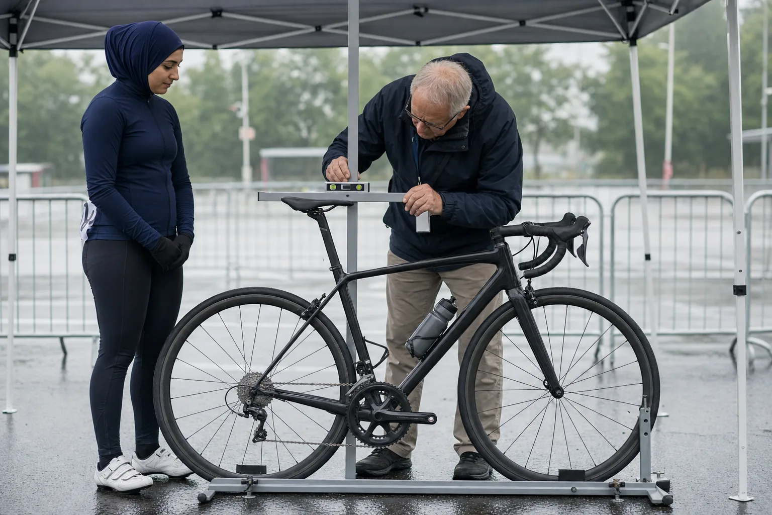
05RulesIn-depth
“UCI-legal” is not the same as a fit result
Race rules constrain where parts can go. They do not establish an individual mechanical target.
Read guideCamera field guide
Three questions. No guarantee.
Visible point
Is the landmark tracked?
Usable clip
Are its cycles usable?
Independent agreement
Do separate takes agree?
Visibility concerns an estimated point; quality concerns a clip.
Independent agreement concerns the recorded condition.
None alone certifies physical accuracy, comfort or installation.
06Camera methodIn-depth
Why this app talks about confidence so much
A phone video has real limits. Honest uncertainty beats a confident wrong answer.
Read guideTopic 0414 guides
Know when to stop
Keep missing or conflicting component limits unresolved; ask the exact manufacturer or mechanic before changing an assembly.
Same torque. Different numbers.
- N·m
- 4.00
- N·mm
- 4000
- lbf·in
- ≈35.40
Original reference ledger, not to scale or an installation drawing. Resolve exact joint, receiver, source, preparation and tool conditions. No tightening or physical work is performed.
Torque referencesFeatured field guide
Bicycle bolt torque references: units, ranges and the exact joint
Read the complete specification before recording a torque reference: distinguish N·m, N·mm, inch-pounds and foot-pounds, maximum from a range, and the exact receiving parts and preparation conditions. No tightening value is prescribed.
Read the complete guideAn actuator endpoint is not a tube endpoint.
Original schematic; not to scale. No physical measurement, preferred travel, clearance, control function, compatibility or installation is established.
02Dropper referencesIn-depth
Dropper post insertion: frame depth, actuator and routing are separate constraints
Keep receiving-frame limits, lower-body references, actuator space and routing permission independent. A free depth or matching diameter is not a complete assembly check.
Read guideName each axial pair of reference planes
Original schematic; not to scale. Not a real part drawing, tolerance, conversion, installation or physical inspection.
03Crank interface referencesIn-depth
Bottom-bracket shell standards: BSA, T47 and press-fit are receiving interfaces
Read the frame shell, cup or bearing interface and axial width separately from the crank spindle. Keep nominal family labels, physical observations and exact assembly permission distinct.
Read guideEqual length does not locate the bearings
Original schematic; not to scale. Not a real part drawing, tolerance, conversion, installation or physical inspection.
04Crank interface referencesIn-depth
Crank spindle diameter, length and bearing stations: three different references
Identify the exact spindle variant, name each diameter station and retain axial endpoints and bearing locations independently. Equal diameter and overall length do not establish a complete crank interface.
Read guideOne circle, different adjacent chords
Original schematic; not to scale. Not a real part drawing, tolerance, conversion, installation or physical inspection.
05Crank interface referencesIn-depth
Chainring BCD, asymmetric bolts and direct mount: identify the receiving interface
Separate a bolt-circle diameter from angular spacing and direct-mount families, then keep exact crank generation, offset, tooth profile and whole-system conditions unresolved until supported.
Read guideName the retaining parts
Original schematic; not to scale. Not a real part drawing, tolerance, conversion, installation or physical inspection.
06Wheel mounting referencesIn-depth
Quick release versus thru axle: identify the retention system, not just the lever
Separate a quick-release skewer from the hub axle and a thru axle, identify the receiving fork or frame, and keep each mounting interface unresolved until its exact evidence is available.
Read guideContact span is not shaft length
Original schematic; not to scale. Not a real part drawing, tolerance, conversion, installation or physical inspection.
07Wheel mounting referencesIn-depth
Hub spacing and OLD versus axle length: name the two contact faces
Distinguish hub over-locknut or built-in contact span from internal and retaining axle lengths, keep front/rear and end-cap configurations explicit, and avoid inferring a wheel conversion.
Read guidePitch counts axial intervals
Original schematic; not to scale. Not a real part drawing, tolerance, conversion, installation or physical inspection.
08Wheel mounting referencesIn-depth
Thru-axle length and thread pitch: keep every endpoint and interface explicit
Read axle diameter, source-defined shaft length, pitch, threaded extent, head contact and receiving system separately, without using a matching hub label or trial-tightening as permission.
Read guideMount, radius and thickness stay separate
Original schematic; not to scale. Not a real part drawing, tolerance, conversion, installation or physical inspection.
09Wheel mounting referencesIn-depth
Disc-brake rotor interface, diameter and thickness: three independent references
Distinguish hub rotor mounting from disc diameter and thickness, retain caliper/pad/frame/fork and lockring conditions, and avoid turning one matching label into brake or wheel approval.
Read guide10Drivetrain referencesIn-depth
Cassette and freehub compatibility: identify the driver before the speed count
Separate cassette tooth sequence, driver interface, exact hub-body permission and whole-drivetrain compatibility; a matching speed count is not an approval.
Read guide11Drivetrain referencesIn-depth
Rear derailleur total capacity versus maximum sprocket: keep every limit separate
Read total tooth difference, largest/smallest sprocket bounds, front difference and system identity without mistaking one passed calculation for assembly permission.
Read guideSeatpost field guide · not to scale
Minimum and maximum must meet.
Fictional lower max(100,120) = 120 mm; upper min(260,180) = 180 mm.
I = 120–180 mm; named axial L = 320 mm → E = 140–200 mm.
A frame maximum of 110 mm makes the interval empty. This is not a safe installation range.
12Seatpost referencesIn-depth
Seatpost insertion depth and exposed length: minimum is not maximum
Keep engagement requirements, frame/post insertion ceilings and length datums separate. Intersect declared fictional bounds without turning the resulting interval into installation approval.
Read guideWheel reference guide · not to scale
One known field is not a green light.
Identify exact tyre and rim, size, generation, bead construction and use conditions.
Resolve independent diameter, width/type, pressure and assembly requirements.
A tube changes no bead interface. Unknown, excluded or conflicting permission stays unresolved.
13Wheel referencesIn-depth
Hookless and tubeless tyre compatibility: separate every permission
Hookless describes a rim interface; tubeless describes an assembly system. Check exact tyre and rim permissions, width and pressure conditions independently—an inner tube does not resolve an unsupported pairing.
Read guideFlat-bar reference · not to scale
Name the station, then the diameter.
Fictional central stem interface: 35 mm. Separate end grip-area interfaces: 22.2 mm.
Clamp width, uninterrupted end length, material and accessory permissions are separate checks.
These labels are not a compatibility result, actual wall section or installation instruction.
14Flat-bar referencesIn-depth
Handlebar clamp vs grip diameter: identify each flat-bar interface
Separate the stem clamp, grip area, usable straight length and bar-end interface before treating a diameter label as compatibility.
Read guideOpenBikeFit records mechanical setup, compares repeated measurements and presents published reference ranges with their limitations. It is for adults without an active health or injury concern and does not assess symptoms, decide whether riding is medically safe, recommend care or predict health outcomes. Outputs are measurement hypotheses, not verified facts or prescriptions.